12V 10A switching power supply (with schematic and explanation) YouTube
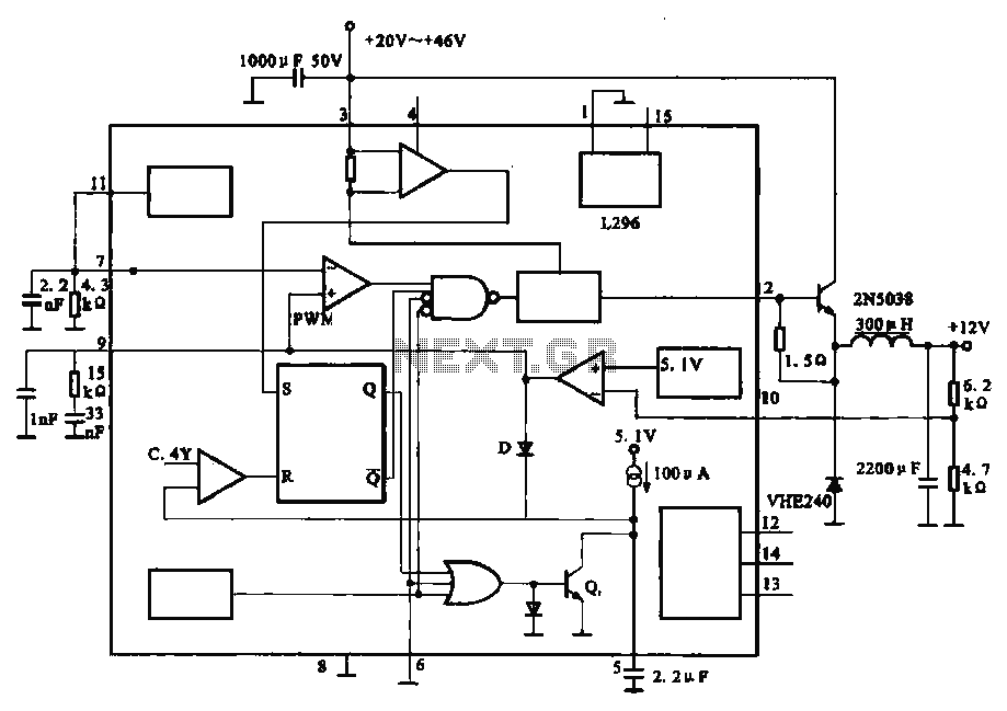
12V 10A switching power supply (with schematic and explanation) Ⅱ The Basic Principle of Switching Power Supply 2.1 The Basic Principle of PWM Switching Power Supply. It is quite easy to understand the working process of the switching power supply. In a linear power supply, the power transistor is operating in a linear mode.
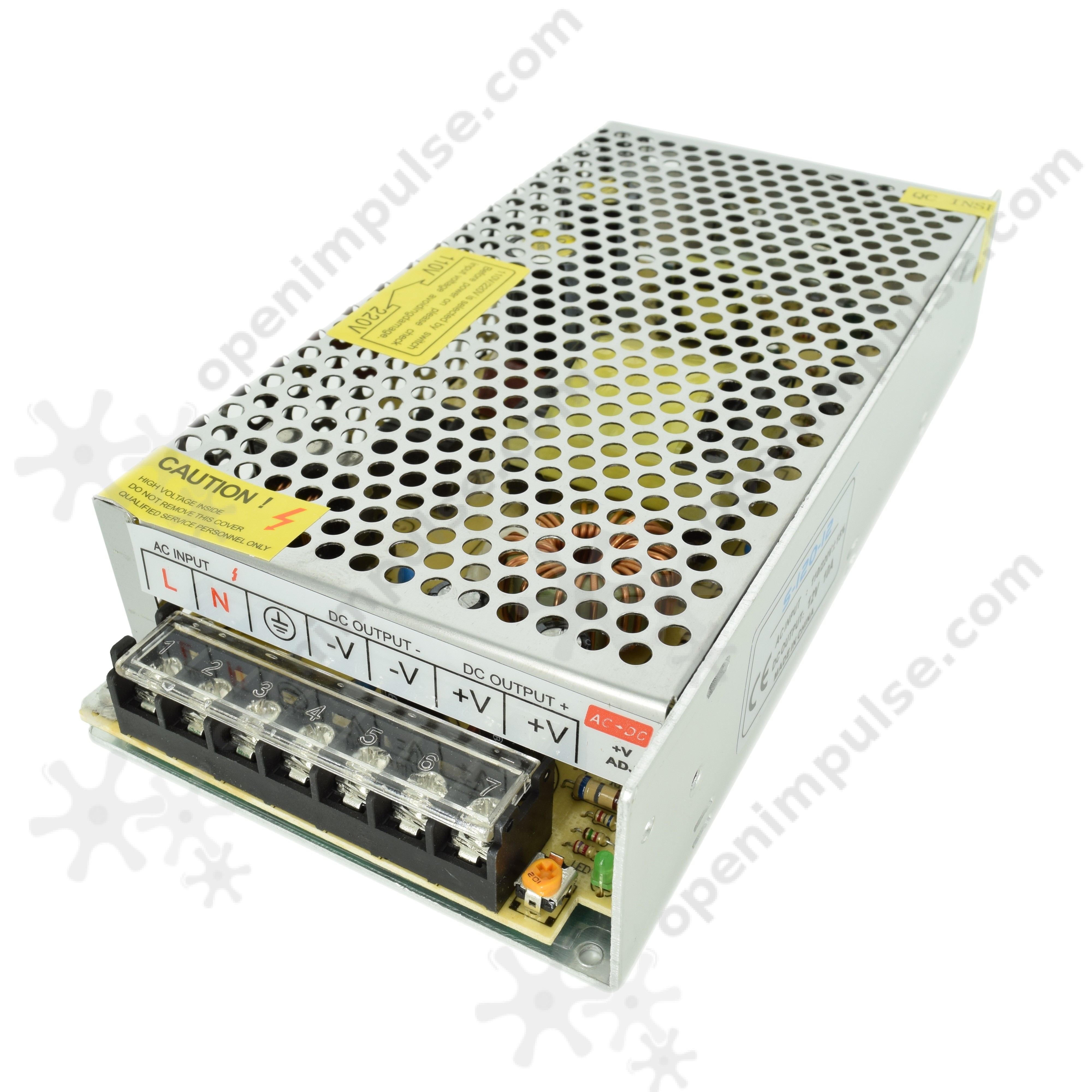
12V 10A (120 W) Switched Mode Power Supply Open ImpulseOpen Impulse
NEMA 6 devices, while specified as 250 V, may be used for either 208 or 240 V circuits, generally depending on whether the building has a three-phase or split-phase power supply, respectively. The NEMA 6-20R or 6-30R found in many hotel and motel rooms is typically supplied with either split-phase or two phases of three-phase 208 V.

12 Volt 10 Ampere DC Power Supply Circuit
One of the key components in a 12V switching power supply is the switching regulator. This device controls the flow of current through the circuit and regulates the output voltage. It does this by rapidly switching the input voltage on and off at a high frequency, then filtering and smoothing the output to ensure a stable 12V DC.
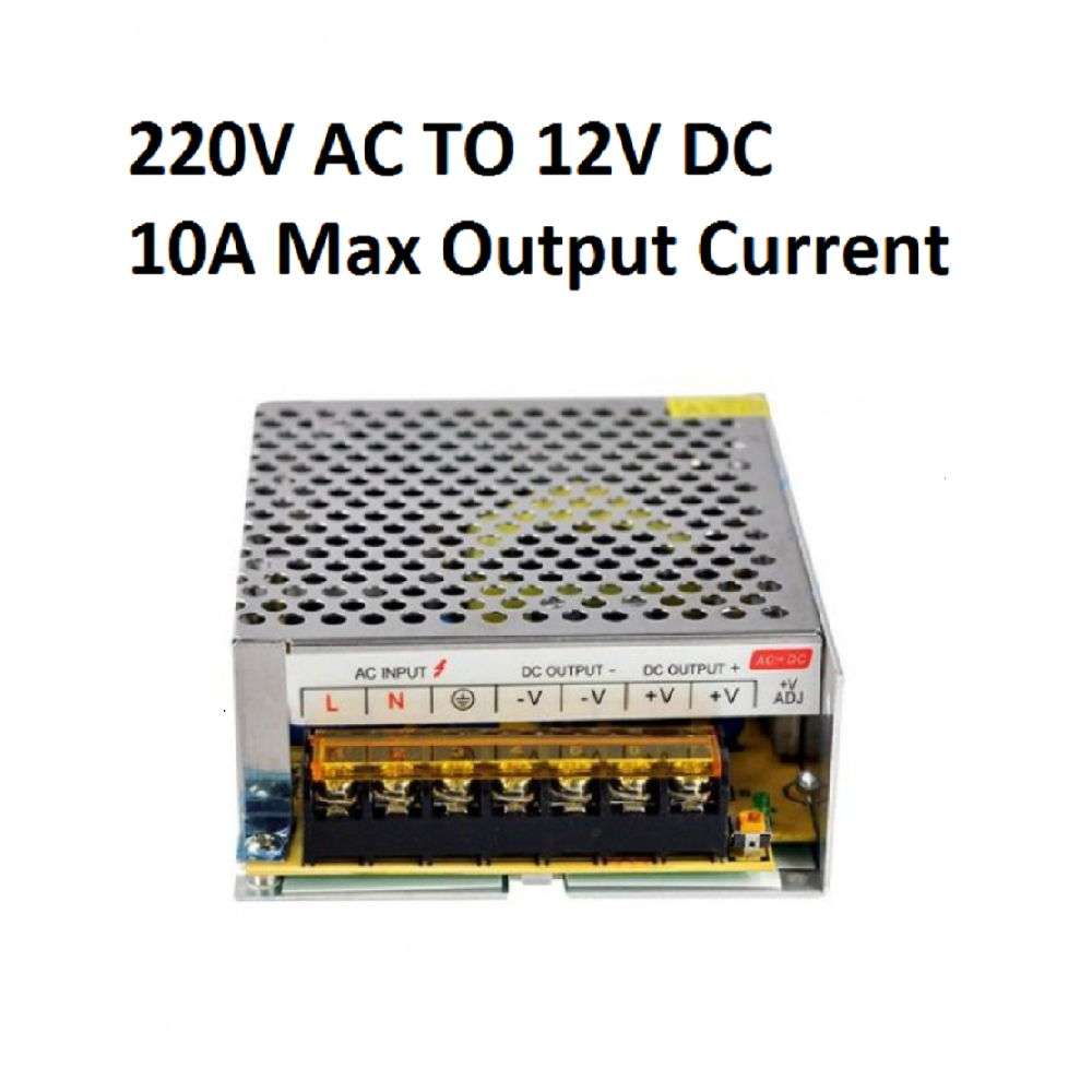
Power Supply 12v 10A
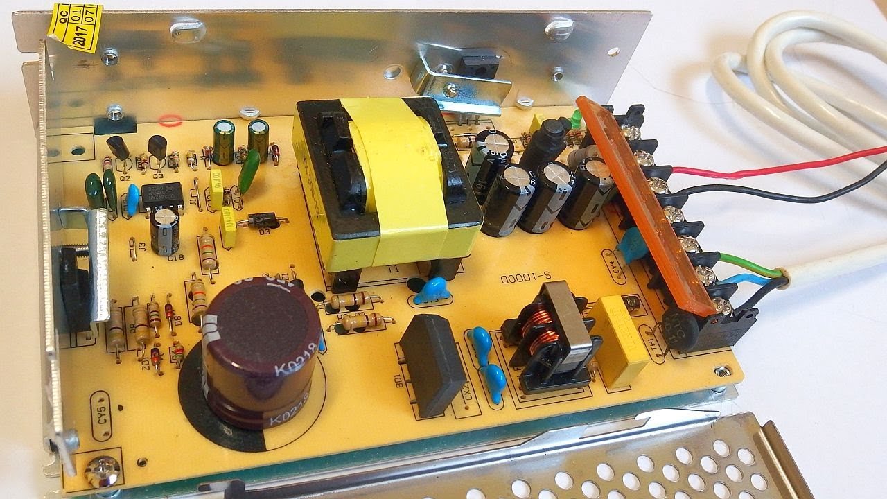
12V 10A switching power supply (with schematic and explanation) 6.4K DiodeGoneWild The schematic in my DB of reverse engineered schematics:http://danyk.cz/reverz44_en.htmlToday I made.

12V、10A regulated power supply composed of LM305 Power_Supply_Circuit
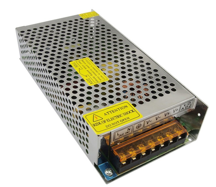
1. Input is AC 100~240V and output is DC 12V 10A 120W. 2. High safety performance, with short circuit, overload, over voltage, protection function. 3. Low working temperature, long service life. 4. Wide input voltage range, in line with global standards. 5. The power supply efficiency is high, and the electromagnetic interference is low. 6.

DIY SMPS Power supply 12V 10A YouTube
1. Efficient Charging: The 12v 10a SMPS battery charger circuit is specifically designed to efficiently charge 12-volt batteries. It utilizes a switch mode power supply, which allows for fast and efficient charging by converting the input AC voltage to a high-frequency AC signal.
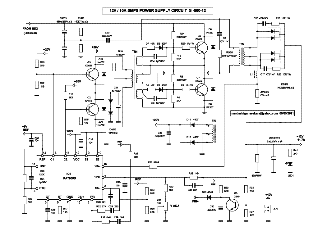
CHINA S50012 12V 10A PSU SCH Service Manual download, schematics
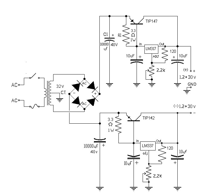
A 12V 10A power supply circuit. 12VDC power supplies are fundamental power supplies with an AC input and 12V DC yield voltage. The yield voltage changes with the input voltage and load. These power supplies are cheap and very dependable.

Reverse Engineered Schematics
12v circuits explanation 3 easy 48v battery charger circuits explained 12v 10a smps circuit diagram. Volt wiring transformer schematics acid electroschematics chargers electrical. topic smps circuit diagram battery chargerPin on power supply circuit. 12v, 5 amp smps battery charger circuit24v to 36v battery charger circuit Switch mode power.
12V, 10A DC Power Supply (SMPS) leetechbd
The 12V 10A power supply circuit diagram is a crucial part of any electronics project. It can be used to power a wide range of devices, from basic electronic components to sophisticated gadgets. As such, it's important to understand how these circuits work and how to create them.
circuit 10a variable power supply symmetric under Repositorycircuits
This is the circuit diagram of 12V / 10A switching power supply. The circuit, shown in the schematic, provides 12 volts, at 10 amperes, maximum, using a discrete transistor regulator with an op-amp functioning as a comparator in the feedback circuit.
Output 12V10A power circuit under ACDC & DCDC Circuits 57071 Next.gr
This is 12V 10A regulated Power supply circuit with PCB Layout. We use LM723 HIGH PRECISION VOLTAGE REGULATOR and 2N3055 power NPN transistor as main parts. The two 2N3055 x 2 to increase current up form LM723. We need to use 10A transformer, the power transistors to hold Heat-sink. In circuit, we can adjust easily the output voltage with VR1 - 1K.

10A Laboratory Power Supply Circuit Engineering Projects
Now, we have to define which outputs will be able to provide the 10Amps, i decided to make 2 boards, 10A board, with 5v and the variable 0 to 25v both will be able to output up to 10Amp. OPAMPS Board, with fixed -12v, 12v, and a variable negative outputs, the 3 of them limited to 1 Amp. These last 3 will be limited to the maximum output current.
12V 10A DC Power Supply SMPS Custom Electronics, PWM Circuits
Here this circuit diagram is for +12V regulated (fixed voltage) DC power supply. This power supply circuit diagram is ideal for an average current requirement of 1Amp. This circuit is based on IC LM7812. It is a 3-terminal (+ve) voltage regulator IC. It has short circuit protection , thermal overload protection.

12v 10a Power Supply Circuit Diagram
Please make a donation if you would want to support this YouTube channel:TRk3JFBDhskBH1NXeinPtGxH4U7x3wuyee(USDT TRC20)Circuit project files : https://drive..

12 Volt 10 Ampere DC Power Supply Circuit
The 12v 10 Amp SMPS circuit diagram is used to supply regulated power to most electronic devices, providing electrical isolation between the power source and the load. It's an ideal solution for anyone who wants a reliable and dependable power supply for their electronic equipment. The 12v 10 Amp SMPS circuit diagram is fairly easy to create.

12v 10a Power Supply Circuit Diagram
The 12V 10A regulated power supply schematic is a rather simple entity. It consists of two transistors, one for current flow (the NPN transistor) and one for voltage regulation (the PNP transistor). Both transistors are connected in series with each other and with a source of voltage.